What is Isometric Projection ? |Difference Between an Orthographic and Isometric Projection
What is Isometric Projection? | Difference Between an Orthographic and Isometric Projection | Advantages of Isometric Projection | Difference Between Isometric View and Isometric Projection
What is Isometric Projection?
An isometric projection is the perspective representation of an object placed so that the three significant edges (which correspond to the three dimensions of the object) form equal angles of 120.
Unlike multi-view projection, isometric projection allows you to represent all three dimensions of an object. It, therefore, involves the use of perspective.
One does not find any horizontal edge in this type of projection. Consequently, no face of the object is parallel to the sheet.
Instead, the object has one or more edges in the foreground. In this type of projection, the visual rays are perpendicular to the drawing sheet while the object is tilted relative to the latter.
Advantages of Isometric Projection
The advantage of this type of projection is that all measurements of edges parallel to isometric axes (the axes corresponding to the three dimensions of an object) correspond to the scale at the actual lengths.
Therefore, we can rely on the dimensions of an isometric projection to know the real dimensions of an object.
💥🎁 Christmas & Year-End Deals On Amazon !
Don't miss out on the best discounts and top-rated products available right now!
🛒 Shop Now and Save Big Today!*As an Amazon Associate, I earn from qualifying purchases.
However, the measurement of the object’s angles is not respected, and it happens, in some instances, those specific shapes are distorted (for example, the circles become oval).
Difference Between an Orthographic and Isometric Projection
The difference between these types of views lies in the fact that, in the Isometric Projection, the objects have different sizes depending on the distances they are from one another.
In other words, in the Orthogonal or Orthographic view, we cannot notice the difference in size regardless of the objects’ distance.
Applications of Isometric Projection
The figures on the left are the views in a dihedral system, while on the right, an isometric projection with a partial section is seen.
In design and technical drawing in industrial design, a piece is represented from different points of view, perpendicular to the natural coordinate axes. Apart mechanical movement generally has shaped with axes of symmetry or flat faces. Such axes, or the edges of the faces, allow defining an orthogonal projection.
An isometric perspective of the part can easily be drawn from such views, allowing for a better understanding of the object’s shape.
💥🎁 Christmas & Year-End Deals On Amazon !
Don't miss out on the best discounts and top-rated products available right now!
🛒 Shop Now and Save Big Today!*As an Amazon Associate, I earn from qualifying purchases.
Isometric Projection in Architecture
The Louvre’s castle, isometric drawing by Violle, used this system in many drawings of his buildings, avoiding accentuating the importance of some volumes over others and making it independent from the observer’s point of view.
The perspective of this drawing of the castle is not isometric; if it were, the castle towers would be drawn with the same height and diameter.
Besides, the roofs’ ridgelines would be parallel to each other, forming a rhombus or rhomboid depending on the castle floor.
In videogames, several videogames put their characters into action using an isometric point of view, or rather, in the usual jargon, in “3/4 perspective”.
From a practical angle, this allows you to move the graphic elements without changing the size, an inevitable limitation for computers with low graphic capacity.
To avoid pixilation, in some cases, the projection was taken to a 2: 1 system, that is to say, at a 26.6º inclination (arctan 0.5) instead of 30º, which does not correspond to an isometric projection itself, but “diametric.”
💥🎁 Christmas & Year-End Deals On Amazon !
Don't miss out on the best discounts and top-rated products available right now!
🛒 Shop Now and Save Big Today!*As an Amazon Associate, I earn from qualifying purchases.
The progressive increase in computers’ graphic capabilities has made possible the increasingly widespread use of more realistic projection systems, based on the perspective naturally perceived by the human eye: the conical perspective.
Common Uses of Isometric Projection
Because isometric projection keeps the relative proportions of an object the same on all three axes, it is commonly used in architectural and technical drawings to allow in-plane measurements to reflect the real object or building measurements accurately.
The aerial isometric perspective is also used in many computer games.
No more than four sprites are required to represent any game object, and it allows game characters to travel any distance without needing to change perspective.
Isometric Projection FAQs
What is the isometric projection in engineering drawing?
The isometric projection is a type of parallel projection in which three of the axes are orthogonal and the diagram appears to be tilted at an angle.
Isometric projections are often used in technical drawing to show mechanical parts or 3D objects.
💥🎁 Christmas & Year-End Deals On Amazon !
Don't miss out on the best discounts and top-rated products available right now!
🛒 Shop Now and Save Big Today!*As an Amazon Associate, I earn from qualifying purchases.
The use of this type of projection was first introduced by Leon Battista Alberti in his 1435 manuscript De Pictura, where he called it “perspective.”
How does one make an isometric projection?
Draw a vertical line on the sheet with the ruler and mark three evenly spaced spots along with it.
Draw a horizontal line across the lowest point and mark a 30-degree angle up from the line on either side with a protractor.
Draw a line from the 30-degree angle on each side back through the lowest point.
What is an Isometric Projection Drawing?
An Isometric Projection Drawing is a drawing that is created in which the third dimension is shown. To create this type of drawing, first draw a box with its six sides on a piece of paper.
Then, tilt the box slightly and use circular arcs to connect each corner to form three sides parallel to the ground.
💥🎁 Christmas & Year-End Deals On Amazon !
Don't miss out on the best discounts and top-rated products available right now!
🛒 Shop Now and Save Big Today!*As an Amazon Associate, I earn from qualifying purchases.
Now, you can draw your object on each side of the cube separately and show what they would look like from different angles.
What is the difference between isometric and isometric projection?
An isometric projection of an entity is a common visual projection in which the object is positioned so that all three axes of the object are equally inclined to each other.
ISO stands for “equal.” METRIC is an abbreviation for “measure.” As a result, isometric refers to equal measurement.
What is an isometric projection example?
Fundamentally, an isometric projection is a two-dimensional depiction of a three-dimensional object with three main lines that are all equally slanted away from the spectator. A technical sketch of a home or structure is an example of isometric projection.
The term “isometric” derives from the Greek meaning “equal measure,” referring to the fact that the scale along each axis of the projection is the same (unlike some other forms of graphical projection).
An isometric view of an item may be achieved by orienting the camera in such a way that the angles between the projections of the x, y, and z axes are all equal, or 120°.
💥🎁 Christmas & Year-End Deals On Amazon !
Don't miss out on the best discounts and top-rated products available right now!
🛒 Shop Now and Save Big Today!*As an Amazon Associate, I earn from qualifying purchases.
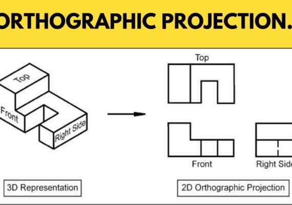
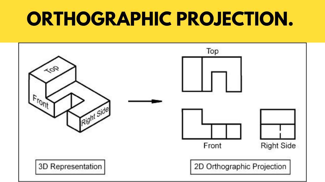
What are the 3 views of isometric drawing?
They usually depict an object from three separate perspectives (Usually the Front, Top, & Right Side).
Each of the views is rendered in 2-D (two dimensions) and has dimensions marking the object’s length, breadth, and height.
What exactly does the term “isometric drawing” mean?
Isometric drawing, also known as isometric projection, is a way of graphically representing three-dimensional objects used by engineers, technical illustrators, and, on rare occasions, architects. One type of orthographic projection is isometric.
What is the isometric projection principle?
It is a visual orthographic projection of an item in which a clear cube representing the object is tilted until one of the cube’s solid diagonals becomes perpendicular to the vertical plane and the three axes are equally inclined to this vertical plane.
What is an isometric paper used for?
The isometric paper is used for creating an isometric drawing or sketch of a given object. You need to make sure that you draw every segment in the same direction.
Isometric paper may be used to design 3D forms, such as the cube below, which is made with dots as a guide. The vertical lines are always straight, while the horizontal lines are angled.
💥🎁 Christmas & Year-End Deals On Amazon !
Don't miss out on the best discounts and top-rated products available right now!
🛒 Shop Now and Save Big Today!*As an Amazon Associate, I earn from qualifying purchases.
Isometric drawings may be used to demonstrate a product’s scale as well as a 3D representation.
What is the difference between isometric view and isometric projection?
Isometric views are drawings of objects in which the height, width and depth are drawn to scale.
An isometric projection is a method for visually representing three-dimensional objects in two dimensions.
The term “isometric” comes from the Greek word “iso”, meaning equal, and “metric”, meaning measure.
Isometrics can be applied to anything that can be drawn or modeled on a computer; they are very popular among architects who use them to plan buildings before committing to more expensive renderings.
The difference between an isometric view and an isometric projection lies in how you create it:
💥🎁 Christmas & Year-End Deals On Amazon !
Don't miss out on the best discounts and top-rated products available right now!
🛒 Shop Now and Save Big Today!*As an Amazon Associate, I earn from qualifying purchases.
A 3D modeler will typically use one with more detail while an architect will lean toward the other when designing their building plans.
What is the difference between orthographic and isometric projection?
The three “dimensions” of an object are shown in three orthographic perspectives, each of which shows the thing from one of three perpendicular planes.
An isometric drawing is a quasi-3D drawing that depicts the height, breadth, and depth of an object in a single view with the viewpoint at a 45 degree angle from each of the orthographic view’s perpendicular planes.
Isometric views differ from perspective views in that all lengths are displayed in their real length.
Objects shown as more distant in a perspective drawing are shortened to make the view appear more realistic.