How to Identify Zero Force Members Within a Truss?
How to Identify Zero Force Members Within a Truss?
What is a Zero Force Members?
A zero force member in a truss is a member or segment that experiences no axial force under the applied loading conditions.
A zero force member experience no axial load under a specific loading condition due to the geometry and arrangement of members, even though it contributes to structural stability. Identifying them is key for efficiently analyzing trusses.
Some key points:
- Zero force members are typically identified through inspection of the truss geometry and joint configurations.
- They occur due to redundant members or symmetrical geometry resulting in cancelling forces.
- Conditions for zero force members:
- Joint with only two non-collinear members
- Three members meeting at a joint with two collinear members
- Members cantilevered beyond a support
- External loads passing through a member
- Zero force members are important because:
- They allow simplified analysis by removing them from the model.
- Identifying them indicates indeterminacy and redundancy in a truss.
- They confirm determinacy of a truss.
- Zero force does not mean the member has no purpose. It still provides structural stability.
- Confirmation of zero force is done through joint equilibrium equations or a full truss analysis.
- Zero force members may not remain zero force if loading conditions change.
Following these rules allows zero force members to be identified quickly just by visual inspection of the truss geometry. Confirmation can be done through analysis of joints. Removing zero force members simplifies the truss for further analysis.
Here are 5 key points on how to identify zero force members within a truss:
- Examine each joint in the truss structure. A joint is where two or more truss members meet.
- If a joint only has two non-parallel members meeting, and there are no external loads or support reactions applied at that joint, both members must be zero force.
- If three members meet at a joint, and two of those members are collinear (lie on the same line), then the third member that is not collinear must be a zero force member.
- Identify any cantilevered members – members that extend beyond a support point with no other members. These are zero force members.
- Draw the free body diagram of joints where external loads are applied. If the external load passes through a member, that member will be zero force at that joint.
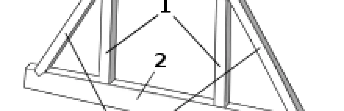
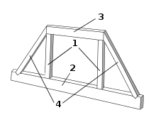
Zero Force Member Examples
Zero force members in trusses are members that carry no force due to the geometry of the truss and how the loads are applied.
💥🎁 Christmas & Year-End Deals On Amazon !
Don't miss out on the best discounts and top-rated products available right now!
🛒 Shop Now and Save Big Today!*As an Amazon Associate, I earn from qualifying purchases.
There are two main rules for identifying zero force members in trusses by inspection:
· If a joint has only two non-collinear members meeting at it and there are no external loads applied at the joint, both members must be zero force members. This is because with only two members, if one member was not zero force, it would lead to unbalanced forces at the joint.
· If three members meet at a joint and two of the members are collinear (in a straight line), then the third member that is not collinear must be a zero force member. This is because the collinear members can balance each other’s forces without need for a force in the non-collinear member.
Identifying zero force members allows for simplified analysis of trusses. Once zero members are known, they can be removed to make a simpler structure to analyze. Removing zero force members does not affect the forces and reactions in the remaining members.
Common examples of zero force members occur in triangular truss configurations where the geometry leads to members that must be zero force, as well as in redundant trusses where strategic member placement leads to zero force members.
Zero Force Members Rules
Remember to draw free body diagrams and apply equilibrium equations to confirm zero force members when in doubt. These rules allow most zero force members to be identified quickly.
💥🎁 Christmas & Year-End Deals On Amazon !
Don't miss out on the best discounts and top-rated products available right now!
🛒 Shop Now and Save Big Today!*As an Amazon Associate, I earn from qualifying purchases.
Here are the key rules for identifying zero force members in trusses:
- Two-Member Joint Rule: If two non-parallel members meet at an unloaded joint, both members must be zero force members. This is because there are no other members to balance out the forces.
- Three-Member Joint Rule: If three members meet at a joint and two of the members are collinear (lie on the same line), then the third member that is not collinear must be a zero force member.
- Cantilever Rule: Any members that cantilever or extend beyond a support point without any other members connected must be zero force members.
- External Load Rule: If an external load passes through a member at a joint, that member is a zero force member at that joint.
- Reaction Force Rule: Members with no external restraint at a joint and only subjected to reaction forces at the joint must be zero force members.
- Geometric Symmetry: Members may be zero force due to symmetrical geometry leading to cancelling of forces on either side.
- Insufficient Members: If joints have insufficient non-parallel members to achieve equilibrium, members must be zero force.
What Is A Non Collinear Members?
A non-collinear member in a truss refers to a member that is not arranged in a straight line with other members at a joint.
A non-collinear truss member is critical for creating a stable, 3D truss structure and enables the use of zero force member analysis principles.
Specifically:
- In a truss, the members are connected at joints where two or more members meet.
- If two members at a joint are collinear, it means they are aligned in a straight line through the joint.
- A non-collinear member means that member is angled or offset from the line created by any collinear members at that joint.
Some key points about non-collinear members:
- Having non-collinear members at a joint is what allows the forces to be transferred in multiple directions through a truss structure.
- If all the members at a joint were collinear, the truss would not be stable as forces could only be transferred along that one line.
- Non-collinear members play a key role in identifying zero force members. At a joint with only two non-collinear members, both members must be zero force.
- Drawing a free body diagram and showing the non-collinear members helps visualize how the forces are transferred through that joint.
💥🎁 Christmas & Year-End Deals On Amazon !
Don't miss out on the best discounts and top-rated products available right now!
🛒 Shop Now and Save Big Today!*As an Amazon Associate, I earn from qualifying purchases.

